The graphic editor window serves both as a pre- and post-processor for MODFE and RADFLOW programs. As a pre-processor, it allows specifying:
•heterogeneity zones,
•initial conditions and
•boundary conditions on the numerical model grid.
The postprocessor allows:
•loading MODFE or RADFLOW output file,
•viewing simulation results and
•saving/exporting simulation results.
In MODFE all the data, except for heterogeneity zones are entered and edited at model nodes, while heterogeneity zones are referred to model blocks.
In RADLOW all the data is entered in model blocks.
The "Input parameters" section summarizes the guidelines to input parameters for each model.
The graphic editor window includes the model grid section, the pumping well section (left of the editor panel) and a series of command buttons placed at the bottom of the editor window.
Model nodes are shown as dots (MODFE). The "2" keay allows zooming in on the nodes, the "1" key allows zooming out, the "3" key restores the original view.
The graphic editor is launched from the main menu through "Numerical models > MODFE > Open model" (or "Numerical models > RADFLOW > Open model"). This command opens a new window where the model to open can be selected.
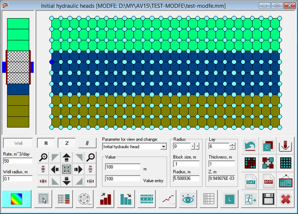
Data input in graphic editor window of MODFE program.
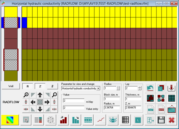
Data input in graphic editor window of RADFLOW program.
Explanatory table
"Well" button |
On/off switch that allows adding/removing the well from the selected layer. SHIFT + click button switches on/off the well in all the layers.
For MODFE: the button is active in heterogeneity zones mode |
"Rate" text box |
For MODFE only Specifies the pumping well rate (m3/day) in the current layer. Discharge corresponds to negative rate value, recharge – to the positive one The text box is active in heterogeneity zones mode |
"Well radius" text box |
For MODFE only Specifies well radius (m) in the current layer. The text box is active in heterogeneity zones mode |
"Parameter to edit" list box |
MODFE Selection of parameter for entry and editing on the grid: heterogeneity zones, initial well head (m), point source rate (m3/day), recharge boundary condition (that is any value used as a mark that can be removed by pushing DEL key). If data are loaded from the output file, the parameter list is supplemented with calculated well head and drawdown. All parameters, except heterogeneity zones are entered and edited in the grid nodes. Heterogeneity zones are attributed to model blocks
RADFLOW Selection of parameter for entry and editing on the grid: horizontal hydraulic conductivity, vertical hydraulic conductivity, storage coefficient, specific yield. If data are loaded from the output file, the parameter list is supplemented with calculated well head and drawdown |
"Value" frame |
The upper text box shows the parameter value in the current block or node. The lower text box contains the parameter input value (stored in memory) to be assigned to any (highlighted) block or node
For MODFE only In heterogeneity zones mode, a list of previously specified zones appears in the lower combo box |
"Radius" frame |
The upper combo box indicates the block number along the R-axis. The "Block" text box indicates the current block size and allows editing its value (for MODFE, this box is active in heterogeneity zones mode)
For MODFE: as data is input to nodes, it shows size of the block just to the left of the node (the first node from the model left edge is the well radius)
The "Radius" text box indicates horizontal distance from the pumping well center 1) to the cursor position (when the mouse is moved); or 2) to the right boundary of the current block (for keyboard navigation through model blocks or left mouse click on the block) or for MODFE 3) to the current node (for keyboard navigation through model nodes or left mouse click on the node) |
"Layer" frame |
MODFE The upper text box indicates the layer number (the first layer from the model bottom is No 1). As data are assigned to nodes, the number corresponds to the layer under the node (the first node from the model bottom is zero). The "Thickness" text box indicates the current layer thickness and allows to edit its value. The text box is active in heterogeneity zone mode. As data are assigned to nodes, the thickness value corresponds to the layer under the node (the first node from the model bottom is zero). The "Z" text box indicates the vertical distance either 1) from the model bottom to the cursor position (when the mouse is moved); or 2) to the current layer top (for keyboard navigation through model blocks or left mouse click on the block); or 3) to the current node (for keyboard navigation through model nodes or left mouse click on a node).
RADFLOW The upper text box indicates the layer number (the first layer is the upper one in the model). The "Thickness" text box indicates the thickness of the current layer (this box allows to edit the layer thickness). The "Z" text box indicates either the vertical distance between the model top and the cursor position (when the mouse is moved), or between the model top and the middle of the current layer (for keyboard navigation through model blocks or left mouse click on a block) |
"R" button |
On/off button allows changing the view of radial (horizontal) grid. At On position a regular grid is displayed |
"Z" button |
On/off button allows changing the view of vertical grid. At On position a regular grid is displayed |
"#" button |
On/off button to switch on/off the grid. At On position the grid is not visible |
|
Lens zooming in the model from the center in every direction, vertically or horizontally. Pushing ALT button + moving mouse left button pressed, displays the frame for zooming the model |
|
Lens zooming out the model from the center in every direction, vertically or horizontally |
|
Shift the model in the specified direction. By pushing CTRL button + moving mouse left button pressed, the model is shifted in the direction of the mouse movement |
|
Cancel the lens and model shift |
|
Cancel changes (made before saving) |
|
On/off copy mode: button on allows to paste the saved values (see "Value" frame) into the selected model block or node |
|
Data import from the file: binary ANSDIMAT data (*.bin) – file previously saved in binary code of ANSDIMAT-compatible format; loads value and color into each block; binary ASCII DATA (*.*) – file in ASCII codes, where the number of blocks along R or Z axes is specified, and values are written by layers; binary Golden Software data (*.dat) – file in dat format; data from the third column is imported |
|
Launches the "Selection" dialog box. Color selection of a data range. Double left mouse click on a bock or node selects all the values equal to that of the current block by a random color |
|
Launches the "Modify values" dialog box. Data substitution and color selection |
|
Pastes the saved value (see "Value" frame) into all blocks or nodes and select them with the current color |
|
Save model data to a file: binary ANSDIMAT data (*.bin) – binary code of ANSDIMAT-compatible format; saves value and color into each block; binary ASCII DATA (*.*) – file in ASCII codes, where the number of blocks along R or Z axes is specified, and values are written by layers; binary Golden Software data (*.dat) – file in dat format; coordinates and of nodes or block center as well as values in nodes or blocks are written |
|
Saves the current model image in bmp format |
|
Creates a new window with the current image (the image is automatically placed into a buffer) |
|
Selects color for data input. The selected color becomes current and paints the blocks or nodes to which the values are input |
|
Takes the current block or nodes color and puts in the memory (shift button + mouse click – the current block value is put in memory) |
|
Launches the "Grouping" dialog box. Data grouping followed by color coding |
|
Launches the "Animation" dialog box. Applied only for data loaded from the input file |
|
Search for block (or node) with maximal parameter value |
|
Searches for block (or node) with minimal parameter value |
|
Launches the "Distance" dialog box. Measures distance between two points |
|
Launches the "Plot" dialog box. Plots 2D plot for by data displayed on the grid |
|
Launches the postprocessor for data output and viewing |
|
Launches the "Generate model grid" dialog box |
|
Launches the "Legend" dialog box |
|
Saves the data and exits from the editor |
|
Saves data without exiting from the editor |
|
Exits from the editor without saving data |


Key functions for left mouse button pressed +
SHIFT |
Parameter input into blocks. A frame appears for color selection and input values stored in the memory into blocks (see frame "Value") |
ALT |
Expands the selected region. A frame appears indicating to which size the model view can be expanded |
CTRL |
Shifts model view along the line of mouse cursor movement |
Mouse double click on the model grid selects blocks or nodes in which the parameter value is equal to that of the current block or node.