See section Multilayered systems (up to 5 pumping aquifers).
Parameters of system are set in the table. The figure shows an example of cross-section with pumping and observation wells.
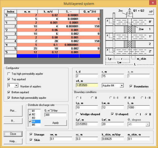
"Multilayered system" dialog box.
Explanatory table
Table |
Thickness (m), hydraulic conductivity (m/d) and storage coefficient (dimensionless) of aquifers and aquitards. Pumping rate for aquifers. A zero pumping rate for aquifer implies the absence of well screen in this interval. Rows white color – aquifers. Rows brick color – aqutards. Tooltips: "Index" column – leaky factor (m) for aquifer (if pumping rate for aquifer more zero) "m" column – total thickness from top of system "k" column – transmissivity (m2/d) and hydraulic diffusivity (m2/d) of aquifer or aquitard "S" column – specific storage (1/m) of aquifer or aquitard |
"Configurator" frame |
Number of aquifers (form 1 to 5) and boundary conditions on the top and the bottom of system |
"t, day" text box |
Time for which drawdown is calculated |
"r, m" text box |
Horizontal Distance from the pumping well to an observation well |
"z, m" text box |
Vertical distance form top of aquitard to observation point in this aquitard (from 0 m to thickness of aquitard) |
"si, m" or "si', m" text box |
This field shows calculated drawdown in the selected aquifer or aquitard |
List |
Select the layer (aquifer or aquitard) in which calculated drawdown |
"Boundaries" option |
Setting boundary conditions |
"I", "II" options at the top of the frame "Boundary conditions" |
Semi-infinite system with boundary condition I kind or II kind |
"I - I", "II - II", "I - II" options |
Two boundaries. For strip, wedge-shaped and U-shaped system. For U-shaped system it is parallel boundaries |
"Lp, m" text box |
Horizontal distance from observation well to boundary |
"Lw, m" text box |
Horizontal distance from pumping well to boundary |
"L, m" text box |
Width of strip system or U-shaped system |
"Wedge-shaped" option |
Wedge-shaped system. Angle is selected in list "θ, degree" |
"U-shaped" option |
U-shaped system |
"I", "II" options near with "U-shaped" option |
Boundary conditions on the third boundary for U-shaped system |
"Lp', m" text box |
Horizontal distance from observation well to the second boundary of wedge-shaped system or the third boundary of U-shaped system. For wedge-shaped system it is distance calculated from r, Lw, Lwc и Lw' |
"Lw', m" text box |
Horizontal distance from pumping well to the second boundary of wedge-shaped system or the third boundary of U-shaped system |
"θ, degree" list |
List of angles: 1, 2, 3, 4, 5, 6, 9, 10, 15, 20, 30, 45 or 90 degrees. For mixed boundaries conditions (I - II) angles 4, 20 and 60 degrees are missing |
"Storage" option |
Сalculation takes into account wellbore capacity |
"Skin" option |
Сalculation takes into account pumping well skin-effect |
"rw, m" text box |
Pumping well radius |
"rc, m" text box |
Casing radius |
"k_skin, m/day" text box |
Hydraulic conductivity of pumping well skin |
"m_skin, m" text box |
Thickness of pumping well skin |
"HP" button |
For wedge-shaped system and U-shaped system show picture with plan |
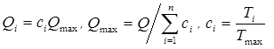
"Distribute discharge rate" frame |
Automatically distribute pumping rate, specified in "Q" text box, for the selected aquifers in the list
n – number of aquifers with pumping well screen, Q – total pumping rate ("Q" text box), Ti – transmissivity of i-aquifer, Tmax – maximum transmissivity of aquifer. |