Aquifers separated by aquicludes. Fully penetrating pumping well. Parameters of system are set in the table. The figure shows an example of cross-section with pumping and observation wells.
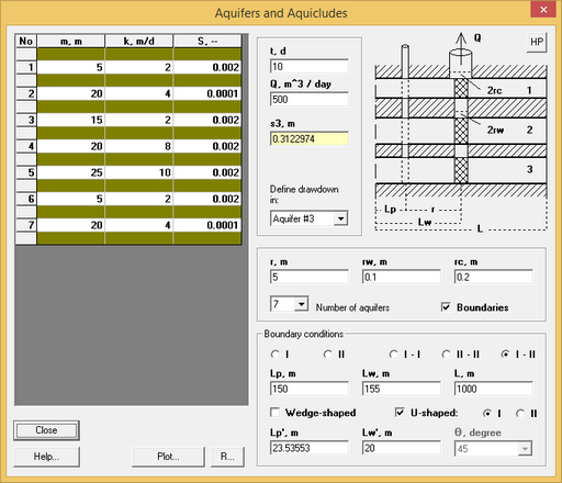
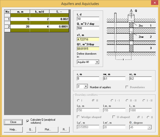
"Aquifers and aquicludes" dialog box.
Explanatory table
Table |
Thickness (m), hydraulic conductivity (m/d) and storage coefficient (dimensionless) of aquifers. Rows white color – aquifers. Rows dark color – aquicludes. Tooltips: "m" column – total thickness of aquifers from top of system "k" column – transmissivity (m2/d) and hydraulic diffusivity (m2/d) of aquifer "S" column – specific storage (1/m) of aquifer |
"t, day" text box |
Time for which drawdown is calculated |
"Q, m^3/day" text box |
Constant pumping rate of a well |
"si, m" text box |
This field shows calculated drawdown in the selected aquifer |
"Qi, m^3/day" text box |
This field shows calculated pumping rate from wellbore capacity and aquifer (#1 or #2). Available for two-aquifers system |
"Define drawdown in:" list |
Select aquifer (or pumping well) in which calculated drawdown |
"r, m" text box |
Horizontal Distance from the pumping well to an observation well |
"rw, m" text box |
Pumping well radius |
"rc, m" text box |
Casing radius |
"Number of aquifers" list |
Number of aquifers in system (from 1 to 13) |
"Boundaries" option |
Setting boundary conditions |
"I", "II" options at the top of the frame "Boundary conditions" |
Semi-infinite system with boundary condition I kind or II kind |
"I - I", "II - II", "I - II" options |
Two boundaries. For strip, wedge-shaped and U-shaped system. For U-shaped system it is parallel boundaries |
"Lp, m" text box |
Horizontal distance from observation well to boundary |
"Lw, m" text box |
Horizontal distance from pumping well to boundary |
"L, m" text box |
Width of strip system or U-shaped system |
"Wedge-shaped" option |
Wedge-shaped system. Angle is selected in list "θ, degree" |
"U-shaped" option |
U-shaped system |
"I", "II" options near with "U-shaped" option |
Boundary conditions on the third boundary for U-shaped system |
"Lp', m" text box |
Horizontal distance from observation well to the second boundary of wedge-shaped system or the third boundary of U-shaped system. For wedge-shaped system it is distance calculated from r, Lw, Lwc и Lw' |
"Lw', m" text box |
Horizontal distance from pumping well to the second boundary of wedge-shaped system or the third boundary of U-shaped system |
"θ, degree" list |
List of angles: 1, 2, 3, 4, 5, 6, 9, 10, 15, 20, 30, 45 or 90 degrees. For mixed boundaries conditions (I - II) angles 4, 20 and 60 degrees are missing |
"HP" button |
For wedge-shaped system and U-shaped system show picture with plan |
"Calculate Q" option |
Calculated drawdown and pumping rate by analytical solution (no Laplace transform solution) |
"Q" button |
Plot of time vs pumping rate |
Wikramaratna R.S. An analytical solution for the effect of abstraction from a multi-layered confined aquifer // Water Resources Research. 1984. Vol. 20, N 8. P. 1067–1074. 2) Wikramaratna R.S. On the components of flow resulting from abstraction in a two-layered confined aquifer with no-cross flow // Water Resources Research. 1985. Vol. 21, N 7. P. 985–989).
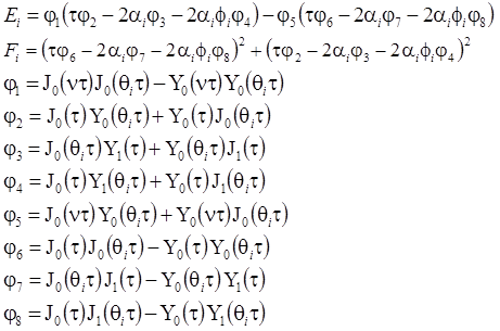
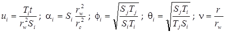
Laplace transform solution:
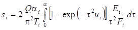
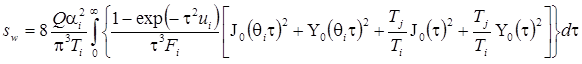
drawdown in i-aquifer
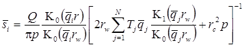

drawdown in pumping well (for r = rw)
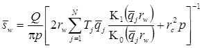
where N – number of aquifers.
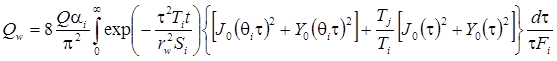
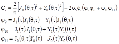
Analytical solution for two-aqufers system:
drawdown in first or second aquifer
i – aquifer in which drawdoun is calculated; j – adjacent aquifer
drawdown in pumping well
pumping rate from first or second aquifer
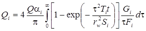
pumping rate from borehole