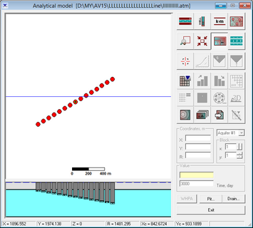
You can input production wells using typical borefield layouts. For this option, use the button "Well system" in the tab "Pumping wells" of the dialog window "Wells and time measurements" (![]() )
)
Frame "Well system" |
User-defined well field layout for pumping wells |
|
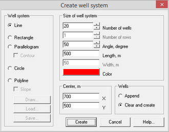
Option "Line" |
Wells are located along a line with specified length |
|
Option "Rectangle" |
Wells are located along several lines, over a rectangular area with specified width, length and rotation angle |
|
Option "Parallelogram" |
This option is similar to the option “Rectangle”, except that rotation angle applies only to two sides out of four |
|
Checkbox “Contour” |
This checkbox is available for options “Rectangle” and “Parallelogram”. When this option is on, pumping wells are assigned along the contour of a rectangle or a parallelogram as two lines |
|
Option "Circle" |
Wells are located along the perimeter of a circle with a specified diameter |
|
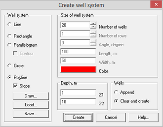
Option "Polyline" |
The pumping wells are assigned along a user-specified polyline at equal distance intervals. When this option is selected, the buttons “Draw”, “Load” and “Save” become available for polylines |
|
Checkbox "Slope" |
This checkbox is active with the “Polyline” option for conceptual models with partially penetrating wells. The selected checkbox allows assigning partially penetrating wells along a profile slope. The depth of the base of the screen in each well is determined in the frame “Depth” and it gradually changes from the initial depth (field "Z1") to the final depth (field "Z2")
|
|
Frame "Depth" |
The frame “Depth” is accessible for “Polyline” option and the checkbox “Slope”. It determines the depth of well screens in a profile along a slope line. Field "Z1" – depth of the base of the well screen for the first well in the group; Field "Z2" – depth of the base of the well screen for the last well in the group. The above field values are measured from the model top and change between 0 and D, where D is the total model thickness |
|
Button “Draw” |
Closes the dialog window and allows drawing a polyline in the graphic widow. The polyline consists of a chosen number of segments. The first interval appears at the start of the polyline drawing. The second and other additional segments are added with a right mouse click. The last added interval can be deleted with a left mouse click. The location of any segment can be changed by placing the mouse cursor on one of the interval’s ends (circle appears) and dragging it to a new position. Shift+Del – deletes the polyline. Esc – saves the polyline and returns to the dialog window |
|
Button “Load” |
Loads saved polyline from another ANSDIMAT project (file polyline.am – see info for the button “Save” below) or from an ASCII file (.DAT or .TXT) |
|
Button "Save" |
Saves polyline in an internal ANSDIMAT format for future use. File polyline.am contains the following info: Number of intervals; Coordinates of intervals: x1, y1, x2, y2 For example, 3 10 20 15 60 15 60 35 47 35 47 72 84 |
|
Frame "Size of well system" |
Defines the dimensions of a well field layout and quantity of wells |
|
Field "Number of wells" or "Number of wells for row" |
Specifies the number of pumping wells in a well field. For the options “Rectangle” and “Parallelogram”, this field specifies the number of wells in each row |
|
Field "Number of rows" |
Specifies the number of lines, along which pumping wells are located for options “Rectangle” and “Parallelogram”. When the checkbox “Contour” is selected, the value 2 is assigned to this field |
|
Field "Angle" |
Specifies the rotation angle of the well field layout in degrees (between 0 and 360). A rotation angle of "0” corresponds to the north-south layout alignment, or from top to bottom of the model area. For circular well field layouts, the rotation angle will rotate a well field clockwise along the circle with specified diameter |
|
Field "Length" or "Diameter" |
Specifies the length of a well field layout in meters. For circular layouts, the circle diameter is specified |
|
Field "Width" |
Specifies the width of a well field layout for the options “Rectangle” and “Parallelogram” |
|
Button "Color" |
Selects a display colour for wells of the well system |
|
Frame "Center" |
Specifies the coordinates (as X and Y) of the well field centre |
|
Frame "Wells" |
Defines how updates are implemented |
|
Option "Append" |
The well system is added to a previously created well system and shown in the graphic interface window “Analytical model”. This option allows updating a modelled well system with additional wells |
|
Option "Clear and create" |
This option deletes all previously created pumping wells and creates a new well system |
|
Button "Create" |
Creates a well system with specified parameters. By default all wells are indexed by their sequential number followed by letters “ws”. Wells appear in the dialog window “Wells and time” and in the graphic interface window “Analytical model”. By default, all wells have the same construction details, that can be changed in the dialog window “Wells and time” |