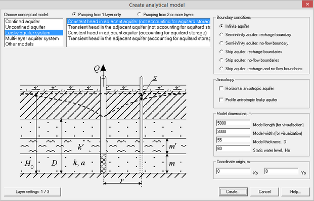
Use the menu File/Analytical models/New model to start a new AMWELLS model. The dialog window displayed (shown below) that includes all the parameters to define a new model. These include conceptual model, boundary conditions, anisotropy, model dimensions, coordinate origin and static water level.
When you click “Create”, a the new model will be saved under the specified name with file extension .atm. It is important that each model is saved in its own specific file folder.

Selecting the conceptual model is a two step process:
– Principal conceptual model (confined, unconfined, leaky aquifer etc.), and
– Detailed conceptual model that specifies further details of the selected principal scheme.
Explanatory table
Option "Pumping from 1 layer only" |
Allows selection of conceptual model for pumping from one layer only |
Option "Pumping from 2 or more layers" |
Allows selection of conceptual model for pumping from two or more layers (i.e. multi-layered aquifer systems). Quantity of layers, between 1 and 5, is determined by user |
List "Choose conceptual model" |
This list is available only for the option “Pumping from 1 layer only”. It consists of two sub-lists: the principal conceptual model and additional pumping conditions. 1. Confined aquifer a. Fully penetrating well b. Partially penetrating well 2. Unconfined aquifer 3. Leaky aquifer system a. Constant head in the adjacent aquifer (not accounting for aquifer storage) b. Transient head in the adjacent aquifer (not accounting for aquifer storage) c. Constant head in the adjacent aquifer (accounting for aquifer storage) d. Transient head in the adjacent aquifer (accounting for aquifer storage) 4. Multi-layer aquifer system: a. Three-layer system with aquifers at the top and the bottom layers b. Three-layer system with aquitards at the top and at the bottom layers c. Three-layer system with aquifer at the top or at the bottom layers d. Two-layer system: aquitard between two aquifers e. Two-layer system: aquitard between aquifer and aquiclude 5. Other conceptual models, including a. Two-layer unconfined aquifer b. Areally heterogeneous aquifer c. Pumping near a river |
Button "Layer settings" |
This button is only accessible for option “Pumping from 1 layer only”. Pressing this button allows specifying additional conceptual conditions for a selected model |
Frame "Configurator" |
The frame is available for multi-layered aquifer systems only (option “Pumping from 2 or more layers"). Allows settings for multi-layer system. Prompts choosing quantity of layers and boundary types for the top/bottom layers. The top/bottom layer can be of the following three types: 1) unlimited storage layers (i.e. water level doesn’t change during pumping), 2) low-permeable layers, 3) non-permeable layers. The third type of layer is available when the top/bottom low-permeable layer is switched off |
Table/diagram of the modeled layers |
The frame is available for multi-layered aquifer systems only (option “Pumping from 2 or more layers"). The diagram shows the multi-layered profile that is defined in the frame "Configurator". The layers are numbered and indexed from top to bottom in the columns “Number” and “Index”. Pumping wells can be assigned in aquifer layers, but not in aquitard layers |
Frame "Boundary conditions" |
Selection between infinite aquifer and one or two lateral boundaries. Also specifies a type of boundary condition (the 1-st or the 2-nd type). For some conceptual models, solutions are available for infinite aquifer only |
Frame "Anisotropy" |
This option assumes horizontal or vertical anisotropy. The option is available only for some conceptual models |
Frame "Model dimensions" |
Defines model dimensions in meters. The dimensions can be changed at later stages of the model |
Text box "Model length" |
Model length (axis X). This parameter is used only for visualisation purposes and does not impact calculation results |
Text box "Model width" |
Model width (axis Y). This parameter is used only for visualisation purposes and does not impact calculation results |
Text box "Model thickness" |
Distance between the top of the top layer and the base of the bottom layer (indicated by letter “D” on the help sketches). By default, all layers of multi-layered aquifer system have the same thickness |
Text box "Static water level" |
Defines the initial static water level, that is measured from the base of the bottom layer (referred to by H0 on the help sketches). For unconfined aquifers, the static water level is smaller than the model thickness as it corresponds to the thickness of the saturated aquifer |
Frame "Coordinate origin" |
Defines coordinates for the left bottom corner of the model area |