The toolbox calculates inflows into Lines of vertical wells with constant drawdown boundaries, maintained at each well. The tool can also be used to calculate inflows and drawdowns, that are caused by Horizontal Drain Holes (HDH). In this case a slotted HDH can be approximated by a line of vertical wells with screen lengths that are equivalent to the HDH diameter. Calculations are done for linear drains in infinite and limited aquifers. It is possible to install from one to four lines of vertical wells located along the contour of a rectangular area. For other configurations of vertical drains and more complex hydrodynamic conditions, use analytical modeling.
The dialog window can be opened by selecting menu "File > Hydrogeologist workbench > Inflow and drains > Drain holes".
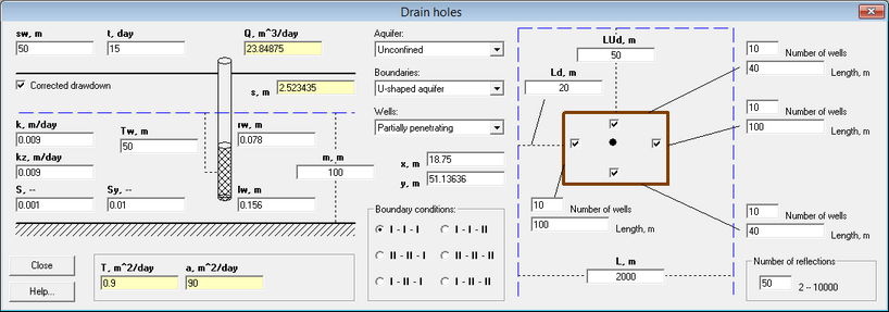
"Drain holes" dialog box.
Explanatory table for dialog window "Drain holes"
"s, m" text box |
Target (constant) drawdown in trench |
"t, day" text box |
Time from start of drainage |
"Q, m^3/day" text box |
Information field that displays total inflow in trench |
"s" text box |
Information field that displays calculated drawdown at the monitoring location (see text boxes "x" and "y") |
"Corrected drawdown" check box |
Drawdown correction in unconfined aquifer (see the formula for drawdown correction in the description of unconfined aquifer). Checking this box is recommended for drawdowns in unconfined aquifers that are equal or above 15-20% of the initial saturation aquifer thickness. The option is available when selecting "Unconfined" in the "Aquifer" list |
"k, m/day" text box |
Hydraulic conductivity of aquifer. For anysotropic aquifer this value corresponds to horizontal hydraulic conductivity |
"kz, m/day" text box |
Vertical hydraulic conductivity for anysotropic unconfined aquifers. This value is also required for partially penetrating wells/trenches |
"S, --" text box |
Confined storage coefficient |
"Sy, --" text box |
Specific yield for unconfined aquifers. This field is enabled only when "Unconfined" aquifer type is selected from the "Aquifer" list |
"B, m" text box |
Leakage factor. This field is enabled only when "Leaky" is selected from the "Aquifer" list |
"m, m" text box |
Thickness of aquifer. For unconfined aquifers this corresponds to initial saturated thickness |
"rw, m" text box |
Radius of a drainage well. It is assumed that all wells have the same radius |
"Tw, m" text box |
Distance from the aquifer top (or from initial water table for unconfined aquifers) to the screen center of drainage well. It is assumed that all wells have the same construction details. This field is enabled only when "Partially penetrating" is selected from the "Wells" list |
"lw, m" text box |
Screen length of a drainage well. It is assumed that all wells have the same construction details |
"T, m^2/day" text box |
Transmissivity of aquifer - auxillary field. If a value is entered in this field, the hydraulic conductivity is automatically updated |
"a, m^2/day" text box |
Hydraulic diffusivity - auxillary field. If a value is entered in this field, the storage coefficient (confined aquifer) or the specific yield (unconfined aquifer) are updated |
"Ss, 1/m" text box |
Specific storage of a confined aquifer. If a value is entered in this field, the storage coefficient is automatically updated |
"Aquifer" list |
Selection of aquifer type from the drop-down list (confined, unconfined or leaky aquifers) |
"Boundaries" list |
Selection of boundary types from the drop-down list: "Infinite aquifer", "Semi-infinite aquifer", "Strip aquifer", "Quadrant aquifer", "U-shaped aquifer". When a boundary type is selected, the boundary lines and distance entry fields appear on the sketch |
"Wells" list |
Selection between fully penetrating and partially penetrating wells |
"x, m", "y, m" text boxes |
The coordinates (m) of the monitoring location (reference point is the upper left corner of the drainage system). The calculated drawdown for this location is displayed in the "s" text box. The position of monitoring location is displayed in the figure as a black circle. The circle moves through the sketch, when changing its coordinates or using the mouse (i.e. left-clicking on the figure inside the drainage system and relocating the mouse to the desired location) |
"Boundary conditions" frame |
Selection of boundary condition types. Number of options depends on number of boundaries (see "Boundaries" drop-down list). Constant Head or Constant Flow can be assigned at each boundary. Dotted line on the sketch corresponds to Constant Head Boundary, while solid line corresponds to Constant Flow Boundary |
"Ld, m" text box |
Distance from the boundary (or the first boundary) to a side of trench |
"LUd, m" text box |
Distance from the second boundary to a side of trench. This option exists for Quadrant aquifer and U-shaped aquifer. |
"L, m" text box |
Width of aquifer for Stripped aquifer or U-shaped aquifer. |
Checkboxes near drains |
Switches one of the four lines of wells on and off |
"Number of wells" text box |
Number of wells by which the lines of wells is approximated |
"Length" text box |
Length of vertical drain. It is assumed that parallel drains have the same lengths |
"Number of reflections" frame |
Maximum number of virtual wells for simulations in Strip aquifer and U-shaped aquifer. The calculations take longer time with higher number of virtual wells |