This dialog window allows determination of unsaturated zone hydraulic conductivity based on infiltration tests in test pits or wells. Interpretation schemes assume that testing is conducted according to standards that are documented in literature (see References) and explained below using schematic illustrations.
The dialog window is opened by menu "File > Hydrogeologist workbench > Infiltrometer tests".
1. Infiltrometer tests in test pits
The method is designed and described by Boldyrev and it involves keeping constant the water level in a test pit located within unsaturated zone (10 cm from the pit bottom is recommended). Hydraulic conductivity is calculated using recorded injection rate that is measured at the time, when steady state is achieved:
![]()
where:
Q - steady state injection rate, m3/day;
F - area of test pit bottom, m2;
delta V - volume of water, m3, that was injected into the test pit during time interval;
delta t - time interval, days.
Nesterov improved the methodology by introducing two rings for the test pit design, that are inserted in the soil. The first (external) ring is inserted deeper than the second (internal) ring. Water is injected between two rings at a rate that is sufficient to avoid horizontal water flow out of the internal ring. Simultaneously, water is injected over the area of the internal ring to achieve constant water level in steady state conditions. The area of the internal ring is used in test interpretation.
To account for capillary forces, the formula of Bindeman is used:
where:
z - depth of infiltration zone from the pit bottom;
H - height of water in the test pit;
Hc - height of capillary rise (assumed the same as the maximum height of capillary rise).
When only one ring is used and capillary forces are not accounted for in calculations, interpreted hydraulic conductivity values may be over-estimated.
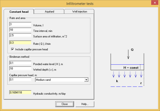
Dialog window that calculates hydraulic conductivity from infiltrometer tests.
Explanatory table
"Volume, l" text box |
Water volume, that is injected in a test pit during a selected time interval (in litres) |
"Time interval, min" text box |
Time interval (in minutes) during which water was injected |
"Surface area of infiltration, m^2" text box |
Ring area through which water was injected. For the Nesterov's method this is the area of the internal ring |
"Rate ( Q ), l/min" text box |
Information field that displays water injection rate. The injection rate is calculated using volume of water and time interval. When value is entered in this field, volume of water is calculated based on defined time interval |
"Include capillar pressure head" option |
When this option is selected, capillary forces (Bindeman formula) are included in interpretation |
"Ponded water level ( H ), m" text box |
Height of water in a test pit. This corresponds to water level that is kept constant during a test |
"Wetted depth ( z ), m" text box |
Depth of infiltration zone from the pit bottom at the and of a test |
"Capillar pressure head, m" text box and list |
Height of capillary rise that is assigned equal to a half of maximum height of capillary rise or selected from the list of capillary rises for different formations. The list is based on data from the Bindeman study |
"Hydraulic conductivity, m/day" text box |
Information field that displays calculation results. While input data are in litres and minutes, calculation results are presented in m/day for user's convenience |
2. Water infiltration through a low-permeable layer
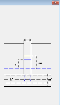
The method assumes that a test well penetrates the top of the low-permeable layer. Water is instantaneously injected in a well and water level changes are recorded. Water levels are assumed to change according to the formula:
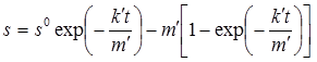
where k', m' – hydraulic cunductivity and thickness of a low-permeable layer; t – time from start of injection; s0 – initial water level in a well (after injection of slug of water).
s0 and s are calculated from the top of a low-permeable layer.
If low-permeable layer is saturated, the soultion becomes as below:
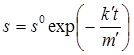
Here, s0 and s are calculated from the water table taht is above the top of low-permeable layer.
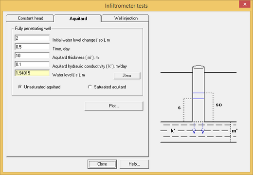
Dialog window that calculates hydraulic conductivity from infiltrometer tests over a low-permeable layer.
Explanatory table
"Initial water level change ( so ), m" text box |
Water level above the top of the low-permeability layer at the initial time (i.e. after water injection in a well). For saturated aquitard, the countdown goes from the initial water level |
"Time, day" text box |
Time from the start of the test |
"Aquitard thickness ( m' ), m" text box |
Thickness of the low-permeability layer |
"Aqutard hydraulic conductivity, m/day" text box |
Hydraulic conductivity of the low-permeable layer |
"Water level ( s ), m" text box |
Information field displaying the predicted water level changes in a well. Water levels are calculated from the top of the low-permeable layer. Negative values correspond to water levels below well bottom |
"Zero" text box |
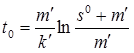
Calculates time t0, when all water infiltrates from a well throgh low-permeable layer and water levels becmes "0". This time is calculated by the formula:
|
"Unsaturated aquitard" and "Saturated aquitard" option |
Selects between two types of initial conditions. The second option assumes that initial water level is above the top of a low-permeable layer, so the layer is assumed confined |
"Plot" button |
Plots changes of water level in a well |
3. Water infiltration in a well penetrating an unconfined aquifer
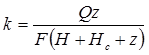
The method assumes that water is injected at a constant pumping rate in a well that fully penetrates an unconfined aquifer. Hydraulic conductivity is calculated by the formula:
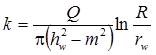
where Q – injection rate of a test well; R – radius of influence of the infiltration test; rw – radius of a well; hw – hydraulic head in a test well from the bottom of an unconfined aquifer; m – initial saturated thickness.
For the case of a deep groundwater table and a testing well partially penetrating unsaturated zone, hydraulic conductivity is determined by the Nasberg solution:
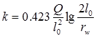
where l0 – height of water table in a test well from the well bottom.
This solution can be only applied when the ration l0/rw is more than 12.5 and less than 50.
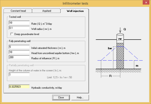
Dialog window that calculates hydraulic conductivity from infiltrometer tests in an unconfined aquifer
Explanatory table
"Rate ( Q ), m^3/day" text box |
Injection rate in the test well |
"Well radius ( rw ), m" text box |
Radius of the test well |
"Deep groundwater level" option |
When this option is off, the well is assumed to fully penetrate an unconfined aquifer. When this option is checked, the well penetration in the unsaturated zone is assumed to be partial |
"Initial saturated thickness ( m ), m" text box |
Initial saturated thickness of the aquifer |
"Head from unconfined aquifer bottom ( hw ), m" text box |
hydraulic head in the test well, that is calculated from the bottom of an unconfined aquifer |
"Radius of influence ( R )", m text box |
Radius of influence of the infiltrometer test |
"Height of the column of water in the screen ( lo ), m" text box |
Height of water in a well during test. Input in this field is enabled for calculations of water injection into a partially penetration well within the unsaturated zone. When the mouse cursor is placed on this field, a context text displays the value of ratio "lo / rw" |
"Hydraulic conductivity, m/day" text box |
Information field that displays calculation results |
References
Справочник гидрогеолога / Под ред. М.Е.Альтовского. М.: ГОСГЕОЛТЕХИЗДАТ, 1962.
Практикум по общей гидрогеологии / Под ред. В.С.Самариной. Л.: Изд-во ЛГУ, 1965.
Методические рекомендации по оценке фильтрационных параметров слабопроницаемых пород при экспресс-опробовании скважин. М.: ВНИИ ВОДГЕО, 1987.