The dialog window "Groundwater mound: strip aquifer" calculates a steady state groundwater mounding caused by recharge, that is homogeneously distributed over the whole area of an unconfined aquifer bounded by two Constant head boundaries, two Constant Flow boundaries or one Constant head boundary and one Constant Flow boundary. Constant head boundaries act as drains (i.e. discharge boundaries) during mounding.
The tool also includes solution for local infiltration that is assigned along a strip area of specified width and infinite length and parallel to the aquifer's boundaries
The dialog window is opened by selecting "File > Hydrogeologist workbench > Groundwater mound > Strip aquifer".
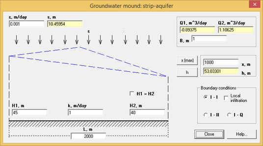
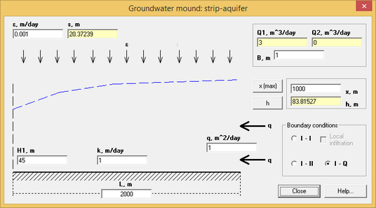
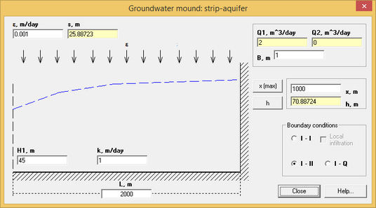
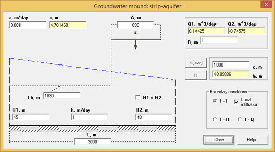
Samples of "Groundwater mound: strip-aquifer" dialog box. Left boundary – Constant Head; Right boundary – 1) Constant Head, 2) Constant Flow, 3) No-Flow. Last sample – local infiltration in a strip aquifer with Constant head boundaries.
Explanatory table
"ε, m/day" text box |
Recharge rate |
"k, m/day" text box |
Hydraulic conductivity of aquifer |
"H1, m" and "H2, m" text box |
Constant Head at the left (1) and the right (2) boundaries. Text box "H2" is enabled only when there are two Constant Head boundaries |
"H1 = H2" option |
After selecting this option Constant Head at the left boundary becomes equal to Constant head at the right boundary. This option is enabled only when there are two Constant Head boundaries |
"L, m" text box |
Width of the strip aquifer |
"A, m" text box |
Width of the local (strip) infiltration area (see options for "Local infiltration") |
"Lb, m" text box |
Distance from the left boundary to the closest boundary of a strip infiltration area (see options for "Local infiltration") |
"q, m^2/day" text box |
Additional flow from the right boundary. This field is enabled when Constant Flow boundary is selected (see option "I - Q") |
"х, m" text box |
X-coordinate of the location to determine mounding "s". Distance from the left boundary along X axis. |
"h, m" text box |
Information field displaying the mounding height at a specified distance "x" from the left boundary |
"x (max)" button |
Determines distance from the boundary to the location with maximum mounding height. The result of this calculation is assigned in text box "x" |
"h" button |
Calculation of the increase in level and head at a given point. A vertical black line appears on the image that moves with the mouse |
"s(max), m" and "s, m" text box |
Information field displaying the maximum height of groundwater mound (smax) and groundwater mound at x-distance from the left boundary (sc). |
"Q1, m^3/day" and "Q2, m^3/day" text box |
Information field to display discharge to the drains on the left (1) and the right (2) boundaries of strip aquifer |
"B, m" text box |
Length of drain for discharge calculations |
"Boundary conditions" frame |
Selection of boundary types for the left and the right sides of a strip aquifer |
"I - I" option |
Two Constant Head boundaries |
"I - II" option |
One Constant Head boundary and one No-Flow boundary |
"I - Q" option |
Constant Head at the left boundary and Constant Flow at the right boundary |
"Local infiltration" option |
Assigns local recharge for a strip aquifer with Constant Head boundaries |
The following analytical solutions are applied:
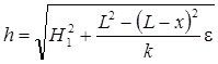
1. Constant Head boundary (I – I)
Hydraulic Head at specified location:
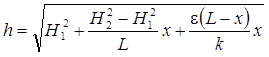
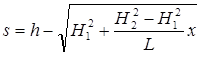
mounding height:
distance from the left boundary to the location with maximum mounding:
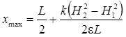
To calculate maximum hydraulic head (mounding) the calculated distance from the above formula should be entered in the formula for hydraulic head (mounding).
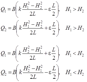
discharge to drain 1 (left boundary) and drain 2 (right boundary) depending on direction of initial gradient:
2. Constant Head boundary and No-Flow boundary (I – II)
Hydraulic Head at specified location:
mounding height:
![]()
maximum Hydraulic Head appears always at No-Flow boundary:
![]()
discharge to drain 1 (left boundary):
![]()
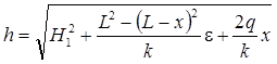
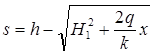
3. Constant Head at the left boundary and Constant Flow at the right boundary (I – Q)
Hydraulic Head at specified location:
mounding height:
maximum Hydraulic Head appears always at No-Flow boundary:
![]()
discharge to drain 1 (left boundary):
![]()
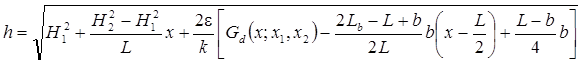
4. Constant Head boundaries with local infiltration:
Hydraulic Head at specified location:
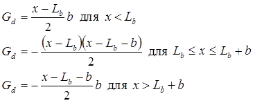
mounding height:

distance from the left boundary to the location with maximum mounding:
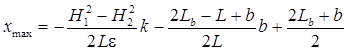
the above formula is for point locations that are inside local infiltration area. Otherwise maximum Hydraulic Head and mounding height will be at the boundary with the highest value of Constant Head.
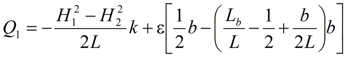
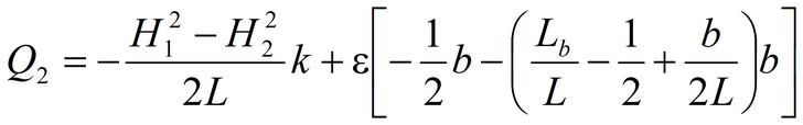
discharge to drain 1 (left boundary) and drain 2 (right boundary):
References
Основы гидрогеологических расчетов. Ф.М. Бочевер, И.В.Гармонов, А.В.Лебедев, В.М.Шестаков. М., Изд-во «Недра», 1969.
Strack O.D.L. Analytical groundwater mechanics. Cambridge University Press, 2017.