Determination of Wellhead Protection Areas with ANSDIMAT
The WHPA module of ANSDIMAT is used to delineate a wellfield’s catchment zones and to generate the Wellhead Protection Areas (or WHPA). Similarly to other models of this type (Blanford and Huyakorn, 1991; Grubb, 1993; Pollock, 2016), ANSDIMAT accomplishes this by introducing a hypothetical “particle” and simulating its movement to a specified point (e.g. wellfield) for a specified period of time. The particle moves in accordance with the program-calculated groundwater velocity along each flow path.
The WHPA module of ANSDIMAT works with hydraulic head distributions that are produced by the analytical models AMWELLS. AMWELLS calculates hydraulic heads and drawdowns at every point of a specified 2-D grid. The heads and drawdowns are produced for a range of simulation times, conceptual hydrodynamic schemes, hydraulic properties and pumping regimes.
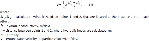
The WHPA module of ANSDIMAT uses AMWELLS results to determine flow paths (as perpendicular to piezometric head isolines – Figure 1) and particle velocity using Formula (1):
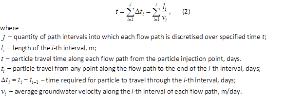
Particle travel times are determined by Formula (2) using lengths of flow paths and calculated groundwater velocities along each flow path
Using formula (2), travel times are calculated for each interval of each particle along flow paths. WHPA zones are delineated by connecting ends of particle travel intervals for specified times (e.g. 400 days for the 2nd WHPA zone or 9131 days for the 3rd WHPA zone). The delineation process is schematically illustrated on Figure 1.
After WHPA zones are determined, the program calculates their areas and also the length and the width of the catchment rectangle. The length of the rectangle (R+r) is equal to the sum of maximum distances from the well (or the well field centre) to the WHPA zone’s up-gradient and down-gradient boundaries. The width of the rectangle (2d on Figure 1) corresponds to the maximum width of the catchment zone.
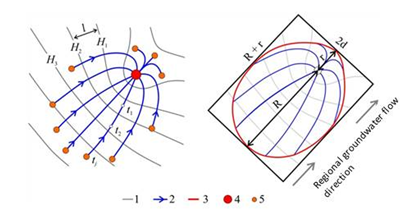
Figure 1. Conceptual sketch of groundwater flow towards the wellfield.: 1 – hydraulic head isoline; 2 – flowpath; 3 – WHPA boundary; 4 – wellfield; 5 – WHPA limit on flowpath.
References
Blanford, N.T. and Huyakorn, P.S. 1991. WHPA: A Modular Semi-Analytical Model for the Delineation of Wellhead Protection Areas. U.S. EPA Office of Ground-Water Protection, Washington, D.C.
Grubb, S. 1993. “Analytical Model for Estimation of Steady-Sate Capture Zones of Pumping Wells in Confined and Unconfined Aquifers”. Ground Water. Volume 31, Number 1. January-February 1993. National Ground Water Association. Dublin, Ohio.
Pollock, D.W., 2016, User guide for MODPATH Version 7—A particle-tracking model for MODFLOW: U.S. Geological Survey Open-File Report 2016–1086, 35 p., http://dx.doi.org/10.3133/ofr20161086.
Calculation of Wellhead Protection Areas (WHPA) is available for all standard conceptual schemes, that are included in ANSDIMAT in exception of the schemes for partially penetrating wells or leaky aquifers accounting for aquitard storage. For multi-layer aquifer systems, WHPA are calculated for the main aquifers (where pumping wells are installed). The detailed list of conceptual schemes is presented in "Conceptual models" section. Further details on calculation methods are provided in Methodology of calculation of WHPA in ANSDIMAT.
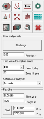
To activate the WHPA graphic window, press the WHPA button. The WHPA toolbox will appear in the right corner of graphical window "Analytical model".

Example of graphical window "Analytical model" after pressing WHPA button.
Explanation notes
|
Draws the WHPA. By default the WHPA is calculated starting from wells. However, when this button and Shift are pressed simultaneously, the WHPA are calculated from model boundaries towards wells |
|
This button enables to run particle tracking from mouse cursor. When this button is on, pressing mouse cursor within the graphical window induces particles that are traced in the forward direction. Traces can be saved as .bln file (Surfer) |
|
Defines hydraulic properties of the model. Opens dialog window "Model parameters" |
|
Options for calculations and display of WHPA. Opens dialog window "Options" |
|
Draws Hydraulic Heads contours based on calculated groundwater flow gradients and directions. Opens dialog window "Groundwater potentiometric map" |
|
Creates an additional window with a copy of the main plot window. Puts a copy of the main plot window in the clipboard |
|
Saves WHPA zones, hydraulic heads and particle traces as ASCII files (*.dat and *.bln). Saves current plot as *.bmp file |
|
Allows zoom in option. Zoom in areas can be selected using mouse cursor |
|
Reverts view scale to full size model after using zoom option |
|
Clears particle traces and plotted WHPA zones |
|
A ruler to measure distances between two points within the graphical window. Opens dialog window "Distance" |
Text box "Gradient" |
Defines natural hydraulic gradient value (dimensionless). This field is inactive when model includes recharge |
Text box "Angle" |
Assigns direction of natural groundwater flow. The direction is defined by an angle (between 0° and 360°). 0° corresponds to groundwater flow from west to east and angle increases anticlockwise. Assigned groundwater flow direction is shown by arrow in the top left corner of graphical window. This field is inactive when model includes recharge |
Text box "Porosity" |
Assigns porosity of aquifer (dimensionless). For areally-heterogeneous aquifer it assigns two values of porosity: n1 and n2. n1 corresponds to the porosity of the main zone, while n2 corresponds to the porosity of the adjacent zone |
Button "Recharge" |
Opens dialog window "Recharge" to assign recharge rate or hydraulic heads at the boundaries of a strip aquifer. Click The text boxes "Gradient" and "Angle" are inactive when model includes recharge. In this case groundwater flow is assumed perpendicular to the boundaries of strip aquifer |
List "Zone II" |
Lookup table for selection of time period (100, 200 or 400 days) for calculation of the 2-nd type of WHPA areas |
Text box "Zone III" |
Assigns a time period (years) for calculation of the 3-rd type of WHPA areas |
List "Accuracy of analysis" |
Accuracy of the calculation of WHPA: rough, average, accurate or manually |
Frame "Pathline" |
Time (years) and length (metres) of particle migration. These fields are available when particle tracking is enabled (particle tracking button is pressed). Text boxes "X" and "Y" – initial coordinates of a particle. Button "Start" – start of particle tracking from the initial coordinates "X" and "Y" When tracking of several particles is required, press buttons "Start" and Shift simultaneously, that opens dialog window "Particles coordinates". Paste coordinates from clipboard (max 100 particles) and press OK |
Button "Close" |
Exit from the WHPA window |
Button Esc |
Stops calculation or drawing processes |
When working with multi-layer systems, the list of layers is displayed at the bottom of the window. WHPA are calculated for the selected layer only.
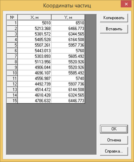
Dialog window "Particles coordinates" that opens after the buttons "Start" and Shift are pressed simultaneously. Data inputs replace existing data in the table.
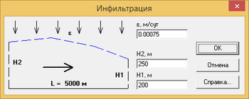
Dialog window "Recharge" that is initiated by the button "Recharge". If one boundary is impermeable, constant hydraulic head is assigned only at one boundary, while hydraulic head at the impermeable boundary is calculated.